The details of processes occurring within fractures and fracture systems require specialized modeling tools. Hydraulic stimulation, chemical interaction, drying or thermal processes will be studied, leading to insights into mechanical behavior that affect fracture generation and growth. The latter activity will build upon existing modeling tools and expertise at IFE, UiB and Uni Research. Data from WP1 are used to constrain models, e.g. chemistry data and mechanical-saturation parameters. Some aspects of these detailed models will be upscaled or used to inform large-scale modeling in WP3.
Tasks in WP2 include:
- Task 2.1: Simulation of leak-off tests (IFE)
- Task 2.2: Fracture modeling with mechanical/chemical processes (UiB/UiO)
- Task 2.3: Coupled thermal and mechanical models (Uni/IFE)
- Task 2.4: Impact of saturation on fracturing behavior (UiB)
Results
Key results focus on various approaches to model fracture activation/propagation, flow and geochemistry. The models are detailed with respect to resolution of the fractures in discrete form that are coupled with the outer matrix. The models are robust and accurate, preserving mass conservation. The models developed in the project are then used to understand processes seen both in the laboratory (core-flooding experiments) or in the field (pressure logs).
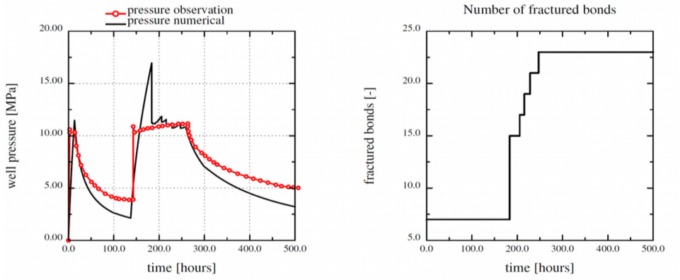
Task 2.1: Simulation of hydrofracturing during pressure testing (IFE) — A fully coupled hydromechanical model has been further developed in the project. The 2D model employs a mixed finite element technique to model fracture mechanics (FEM) and single-phase flow (FV) in a mass conservative, fixed-stress framework (Wangen M, A 2D volume conservative numerical model of hydraulic fracturing. Computers & Structures, 2017). The model utilizes a regular finite element grid at the reservoir scale without any special gridding of the fracture (Fig. 1). A constitutive model for the critical fluid pressure necessary for fracture propagation is based on fracture surface energy. Numerical experiments indicate that most of the fluid injected during hydraulic fracturing resides in the fracture. It is difficult to maintain a fracture pressure when leak-off is dominating the volume of fluid in the fracture. The code has been used successfully to reproduce wellhead pressure during water injection and fracture stimulation in the Adventalen formation on Svalbard, see A numerical model of hydraulic fracturing observed during injection testing of a well in Adventdalen, Svalbard. (180 downloads ) . The modelled pressure is only approximately the same as the observed pressure. The discrepancy is due to the element size and non-linearity of the model (see Fig. 2).

The plots show the stress around a hydraulic fracture that has developed in a heterogeneous rock (Wangen, 2017) (a) The stress σxx and (b) the stress σyy. Negative values give compressive stress. We notice that there is a stress enhancement at the fracture tips. Figure (b) shows that opening of the fracture compresses the rock along its sides.

Fig 2.1 (a) The modelled well pressure is compared with the observed well pressure. The well pressure is shown as the difference between the fluid pressure and the initial reservoir pressure. (b) The number of broken elements as a function of time.
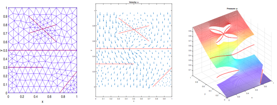
Task 2.2 Fracture-matrix discretization (UiB) — A new, stable and convergent fracture-matrix discretization scheme has been developed in the PhD project hosted by UiB that allows for accurate simulation of flow in finely discretized fractures (see: Boon WM. Conforming Discretizations of Mixed-Dimensional Partial Differential Equations. PhD Thesis, Department of Mathematics, University of Bergen, 2018; and Boon WM, et al. Robust discretization of flow in fractured porous media. SIAM J. Numerical Analysis 2018). The analysis of the fracture flow model has led to a new theory of coupled partial differential equations defined in 3D and 2D, as well as lower dimensions (Nordbotten, JM, et al. Unified approach to discretization of flow in fractured porous media. Computational Geosciences, in press). The method can be solved on non-matching grids and gives more flexibility for modeling fracture-matrix interactions (e.g. discontinuous pressure) as well as including intersecting fractures and dead-end fractures in coupled systems (see Fig. 2.2). The method and its analysis are moreover applicable to problems in 3D (see Fig. 2.2) The scheme has participated in a benchmark study concerning single-phase flow in fractured porous media where it is shown to perform well in comparison to the other participating methods (Flemisch B, et al. Benchmarks for single-phase flow in fractured porous media. Advances in Water Resources 2018).
The same principles are being extended to elasticity problems with thin inclusions, and further development towards poroelasticity is planned. Sharp interface models are closely related to this mathematical framework, especially if the location of the interface is governed by a lower-dimensional, partial differential equation (Boon WM, et al. Efficient Water Table Evolution Discretization using Domain Transformation. Computational Geosciences 2017). This concept has been applied to form a water table evolution discretization based on domain transformation. The domain transformation scheme has been applied to investigate ground flow patterns in the vicinity of meandering streams, both in synthetic model problems as well as a real-world test case (Balbarini N, et al. A 3-D Model of the Influence of Meanders on Groundwater Discharge to a Gaining Stream in an Unconfined Sandy Aquifer. Journal of Hydrology 2017).

Fig 2.2 Example of new fracture-matrix discretization showing gridded fractures with non-matching elements (left). Test problem results for low permeability fractures are shown: velocity profile (center) and pressure distribution (right).
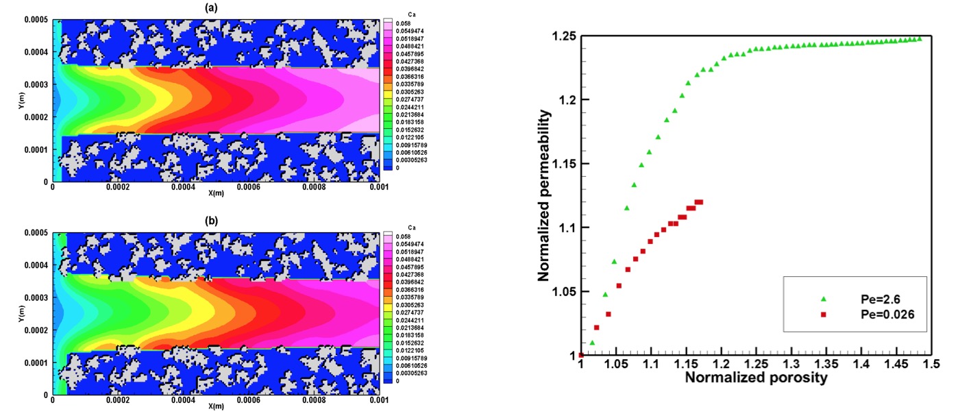
Task 2.2 Reactive transport modeling in fractures (UiO) — Existing lattice Boltzmann (LB) software for pore-scale simulation of reactive-transport processes has been further developed in the PhD project hosted at UiO for dissolution and precipitation reactions relevant for CO2 storage. The extended numerical model has been coupled to the geochemical solver PHREEQC and can be used for 2D and 3D simulations. The model has been used to investigate the alteration of a single fracture surrounded by a heterogeneous rock surface composed of reactive and nonreactive minerals. The mineral composition of the fracture surface was varied to test the impact of heterogeneity on fracture permeability. The presence of non-reactive minerals inhibits uniform dissolution of the fracture surface, thus hindering the impact of dissolution on fracture permeability (Fig. 2.3) (Fazeli H, et al. Effect of Pore-Scale Mineral Spatial Heterogeneity on Chemically Induced Alterations of Fractured Rock: A Lattice Boltzmann Study. Geofluids 2018). Also, the LB solver has been used to simulate the fracture geometry evolution in a fractured carbonate-rich caprock sample. The input geometry for the simulation was taken from CT scan data. 3D simulations also showed that presence of non-reactive minerals can negatively impact the permeability enhancement and that the power law formulations, used for porosity-permeability relations in large scale reactive transport simulators, need to account for presence of non-reactive (or less reactive) minerals in the system (Fazeli H, et al. Three-dimensional pore-scale modeling of fracture evolution in heterogeneous carbonate caprock subjected to CO2-enriched brine, ES&T 2018, in press).
The LB solver is currently being used to simulate the nucleation and precipitation in fracture networks and investigate effect of mineral substrate on the precipitation pattern.

Fig 2.3. Ca concentrations(mol/L) at (a) t = 1.5 hr, (b) t = 4.9 hr. In all three cases Pe= 2.6. Kaolinite mineral is depicted in light gray and zero concentrations (blue) are showing the calcite. Right panel shows normalized permeability vs normalized porosity at two different Pe numbers for initially mixed mineral assemblage (Fazeli et al 2018).
Task 2.4 Saturation-dependent fracturing (UiB): Saturation-dependent processes in deformable porous media requires an understanding of the interrelation between flow and mechanics. A finite-volume numerical model has been developed for two-phase flow and deformation (Varela J. Implementation of an MPFA/MPSA-based solver for unsaturated flow in deformable porous media, M.Sc. Thesis, Department of Mathematics, University of Bergen 2018). Richards’ assumption (inviscid flow of the non-wetting phase) has been applied for the flow problem, while linear elasticity behavior is assumed for mechanics. Unlike saturated flow in deformable porous media (Biot’s equations), unsaturated flow results in a highly non-linear coupled system due to use of water retention curves which are necessary to compute the saturation and relative permeability as a function of pressure. The model has been implemented in Matlab and used to study desiccation processes in clayey soils. Mudcracks form as water evaporates from the soil, shrinking the soil, and inducing stresses above the critical value. We simulate the evaporative process of a clayey soil contained in a Petri dish. Numerical results show an increase in tensile stress as the soil evaporates, with highest stress at the walls of the dish. We can infer that cracks will initiate at the walls and propagate inwards, which is in agreement with experimental results.

Fig. 8. 3D simulation of water evaporation from a clayey soil in a Petri dish (Varela 2018). (Left) Plot shows the evolution of maximum tensile stress that lead to tensile cracks. (Right) The highest values of tensile strength are located on the walls of the Petri Dish where mudcracks would be initiated.