Deformations in the caprock are linked to pressure dynamics in the reservoir and the existing stress states prior to injection. The creation or activation of fractures can occur due to shear and bending stresses from overpressurization, particularly within the damage zone around an existing fault. These impacts create significant risk of leakage, but the dynamics occur at a scale too small to resolve in large-scale models. Upscaling and simplification of sub-grid dynamics will be required, as well as new techniques to couple flow, mechanics and chemistry at the reservoir scale.
Tasks in WP3 include:
- Task 3.1: Upscaling mechanical and chemical effects
- Task 3.2: Coupled flow with leakage with reduced models
- Task 3.3: Large-scale geomechanical deformation modeling
Task 3.1: Upscaling mechanical effects (IFE/NGI/Uni) — A simple analytical 1D poroelastic model has been proposed to estimate reservoir expansion and seabed uplift caused by perturbations of the reservoir pressure (Wangen W, et al. An analytical plane-strain solution for surface uplift due to pressurized reservoirs, Geomechanics for Energy and the Environment, 2018). The validity of the simplified 1D model was examined by plane-strain analysis using the method of Fourier decomposition. The 1D estimate is found to be accurate for pressure wavelengths larger than 2π times the maximum of the reservoir thickness and the overburden thickness. This implies that the 1D estimate will perform better for systems of large areal extent, and with improved accuracy at greater distance from the injection well (see Fig. 3.1). These results, in terms of wavelength, are useful because they identify the amplitudes in a Fourier decomposition of an overpressure distribution that produce reservoir expansion and surface uplift.
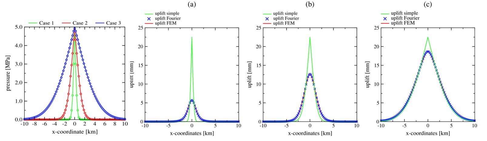
Fig. 3.1. Analysis of simple uplift model (Wangen et al, 2018). (Left) The thick line shows the three pressure distributions of the cases 1, 2 and 3, which corresponds to 0.1, 1 and 10 years of injection, respectively. The circular markers show the Fourier representation of the pressure distributions. (Right) The uplift calculated by three different models created by the three pressure distributions at (a) 0.1 y, (b) 1 y, (c) 10 y.
Task 3.2: Coupled flow with leakage with reduced models (Uni/UiB) — The VESA model (Gasda, et al. Upscaled models for CO2 injection and migration in geological systems. In Simulation of Flow in Porous Media, vol 12, Walter de Gruyter GmbH, Berlin, 2013) developed at Uni Research has been coupled with diffuse brine migration/seepage through a semi-permeable caprock (Aavatsmark I, Gasda SE. Estimation of reduced pressure build-up due to brine seepage using a convolution technique. In proceedings of ECMOR XVI, 3–6 September 2018, Barcelona, Spain). The method employs a classical analytical solution for convective flow through a thick caprock, which applies for caprocks of thickness > 50 meters. The analytical solution is coupled dynamically with the VESA pressure solution in the reservoir. Only brine can seep out of the reservoir, migrating both upwards through the overburden and downwards into the underburden. Brine does not seep into the caprock in locations where the CO2 plume exists. The pressure solution in the over/underburden can be reconstructed analytically to form a fully 3D pressure solution (see Fig 3.2) The fully coupled system has been benchmarked with single-phase analytical solution assuming radial flow in the reservoir. In certain cases, brine leak-off can contribute to significant reduction in overpressure in the reservoir compared to perfectly tight shales with zero leak-off. The magnitude of pressure reduction depends on the reservoir and shale properties as well as the injection rate. Overpressure in the reservoir is reduced with higher caprock permeability, lower reservoir permeability and higher injection rates.
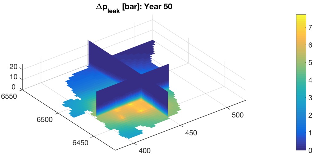
Fig 3.2 VESA simulation of injection into the southern Utsira (Aavatsmark and Gasda, 2018) coupled to analytical solution for brine seepage into the over and underburden. Shown is pressure build-up after 50 years injection at 15 Mt/y. Pressure leak-off increases pressure in the lower 10 meters of the caprock (and underburden, not shown) by 1 to 5 bar.
Task 3.3: Large-scale geomechanical deformation modeling (IFE/NGI) — The simulator has been developed at IFE that solves for deformation and stress from a near-well scale to the basin scale (Wangen M, et al. Geomechanical consequences of large-scale fluid storage in the Utsira formation in the North Sea. Energy Procedia, 2016). The flow is assumed to be single phase, and lithostatic rock properties are homogeneous. The coupled system involves poroelastic stress changes with fluid flow. The fluid flow problem is first solved with a finite-volume method and the mechanics problem is solved with the finite element method using hexahedral elements. The simulator is programmed in the language C, and it has been benchmarked against analytical solutions. The poroelastic fluid pressure equation has the source term expressed with stress, instead of the volumetric strain (fixed stress split). This sequential formulation turns out to be unconditionally stable. Boundary conditions for the pressure equation are impermeable vertical sides and base, and a hydrostatic seabed. The initial fluid pressure is also hydrostatic in the aquifer, the overburden and the underburden. Boundary conditions for the mechanics problem (poroelastic stress change) are free vertical boundaries, free seabed and a fixed base of the model.
A large-scale geomechanical model developed at NGI (Bjørnarå TI, Model development for efficient simulation of CO2 storage. PhD Thesis, Department of Mathematics, University of Bergen, 2018) uses a simplified description of the flow and mechanical processes in the storage reservoir through the method of dimensional reduction. The governing equations for both two-phase immiscible flow and poroelasticity are integrated across the thickness of the reservoir, transforming the relevant variables and equations into integrated and averaged quantities and equations (Bjørnarå TI, et al. Vertically integrated models for coupled two-phase flow and geomechanics in porous media. Water Resources Research, 2016). The equations are solve using FEM in COMSOL Multiphysics software. The dimensionally reduced reservoir is embedded in a three-dimensional environment, accounting for the full stress tensor in the overburden and underburden. The method does not only reduce the number of degrees of freedom that needs to be solved by reducing the dimensionality of the reservoir, it also leads to a less stiff nonlinear system of equations, allowing the numerical solver to progress with longer time steps and consequently further reduce computational time. It has also been demonstrated that the model retains reasonable accuracy when applied to realistic field data as it was tested and validated against a full-dimensional model inspired by the conditions at now decommissioned CO2-storage plant in In Salah, Algeria (Bjørnarå TI, et al. Capturing the coupled hydro-mechanical processes occurring during CO2 injection – example from In Salah. Energy Procedia, 2014). The range of applicability of the dimensionally reduced model is to a leading order the thickness of the reduced domain, the reservoir. A convergence test for a range of aquifer thickness values indicates that accurate solutions in the order of 0.1% and less difference in solution compared to the full-dimensional formulation for reservoirs up to 100-m thick are achieved.
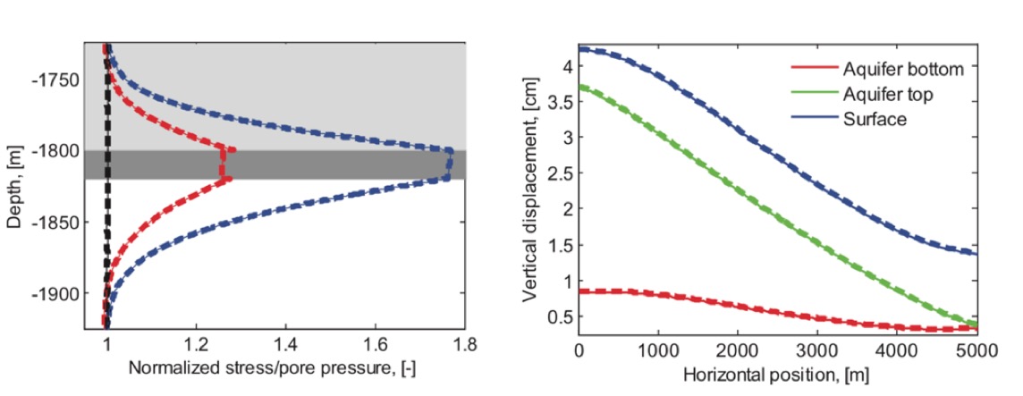
Fig 3.3. Coupled flow and mechanical simulations of reservoir based on In Salah CCS injection using a simplified approach (Bjørnarå et al, 2014) . Left: Vertical profiles of various normalized stress components (normalized to initial values) measured 100 meters away from the symmetry line. Black: vertical stress. Red: horizontal stress. Blue: Pore pressure. Dark gray area indicates the reservoir. Right: Vertical displacement along the bottom of the aquifer (red line), top of aquifer (green line) and surface (surface heave, blue line), cf. Figure 1 (left). In both figure the thin lines are from the simplified model and thick dashed lines are for the fully resolved model.
The analytical 1D uplift estimate presented above (Wangen et al. 2018) can be coupled with VESA, using predicted pressure to estimate ground surface uplift that predict pressure propagation due to CO2 injection. This approach is extremely computationally efficient because there is no need to solve the mechanical system in addition to the flow. Eliminating a full 3D mechanics solve allows one to obtain a better resolution for pressure and saturation in the reservoir than is often possible when fully coupled with mechanics.