Overview
The objective of WP1 is to obtain high-quality datasets on relevant caprock samples. The laboratory tests examine several different parameter sets relevant to classical loading, shearing, and drying mechanisms that are influenced by the presence of CO2. Modeling is performed to interpret the data when necessary. Bench-scale experiments are also performed to provide insight into chemical parameters of fractured rock. Additionally, novel methods for geophysical data interpretation are proposed. The data and process understanding gained in WP1 will be highly relevant for understanding the behavior of fractured shale caprocks like the LYBCO2 pilot site, and for use as parameters in modeling studies in WP2 and WP3. Tasks in WP1 include:
- 1.1 Evaluation of shear characteristics of fractured rock (NGI)
- 1.2: Characterization of fractured rock in triaxial test with CT scan (NGI)
- 1.3: Discrete-element modeling for mechanical parameter calculation (NGI)
- 1.4: Experimental characterization of clay mineral dehydration by dry scCO2 (IFE)
- 1.5: Core-flooding fracture mineralization (UiO)
- 1.6: Joint inversion of complementary geophysical data types (Uni/NGI)
Caprock samples: High-quality core samples preserved in in-situ condtions are essential for accurate representation of hydromechanical and chemical behavior of the caprock samples. Preserved caprock samples are difficult and expensive to obtain. The PROTECT project has access to two sets of preserved core from the Longyearbyen CO2 Lab (LYB) and the CO2 Seal project:
- LYB samples (Rurikfjellet Formation) are generally characterized as stiff, fractured shale (see Brazilian tensile strength test: post-failure behavior of Jurassic and Cretaceous shales from Svalbard (882 downloads ) ).
- CO2 Seal samples (Draupne Formation) are characterized as organic-rich mudstones.
Results
Valuable geomechanical data has been collected in a series of laboratory analyses. The main results to date are focused in shear characterization of pre-fractured caprock samples (Task 1.1 and 1.3) and characterization of shale samples exposed to dry and wet scCO2 (Task 1.4). Results are expected from triaxial tests and core-flooding experiments later in 2017.
1.1 Direct Shear Box: The shear box rig has been mobilized at NGI and the first data have been obtained on three samples from the Rurikfjellet Formation at Longyearbyen CO2 Lab. The samples were tested at dry conditions and with the initial water content. Key results are shown in Figs. 1 and 2. Further details are described in Shear Strength Parameters of Cretaceous Shales from the Cap-rock of the Longyearbyen CO2 Storage Pilot, Svalbard (243 downloads ) .
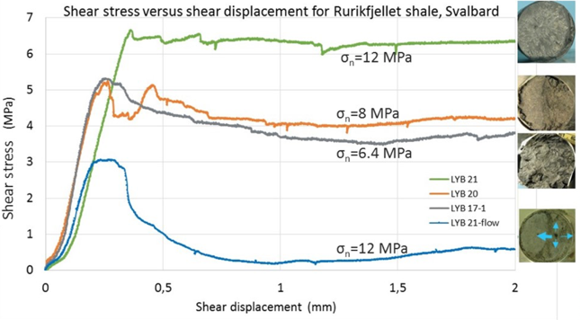
Fig.1. Results from direct shear box testing of Rurikfjellet shale, Svalbard, showing the failure curves under different levels of normal stress. Photos of sheared samples are shown inset.
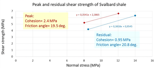
Fig 2. Results from direct shear box testing of Rurikfjellet shale, Svalbard, showing the correlation of shear strength parameters: cohesion and friction angle for both peak and residual portions of the test.
The friction angle was about 16 degrees which is relatively low. Intact shale samples from slightly deeper interval showed a friction angle of 31.5 and cohesion of 3.2 MPa in triaxial test. This discrepancy may be explained by the method of testing, lithological variations or the pre-fractured versus intact samples.
Stress-dependent fracture permeability in artificially fractured caprocks has also been investigated as a function of the flowing fluid. During experiments different fluids (CO2 (gas), water and oil) were injected at different confining pressures (effective stress). Fracture permeability to CO2 (Fig. 2a) shows that organic rich shales are highly stress sensitive and show considerable hysteresis during loading and unloading cycles. This hysteretic behavior can also be shown in cases where there are two subsequent loading and unloading cycles (Fig. 2a). These results imply that fracture aperture may be significantly reduced at deep burial depths. Similar results were seen in another study (van Noort R, Yarushina V. Water and CO2 permeability of a shale core from Svalbard. Energy Procedia, 2016) showing that permeability to liquid/supercritical CO2 is different to that of water or oil (Fig. 2b-c). These results indicate that fracture surfaces undergo alteration, i.e. swelling/shrinking or other surface effects, which impacts the hydraulic properties of fractured caprock material. Studies on shale powder pellets have not seen evidence of direct impacts of swelling/skrinkage on permeability ( van Noort R, Effects of clay swelling or shrinkage on shale caprock integrity. EAGE Annual Meeting, 2018 (45 downloads ) ), but additional research is needed to quantify this effect on natural shale samples.
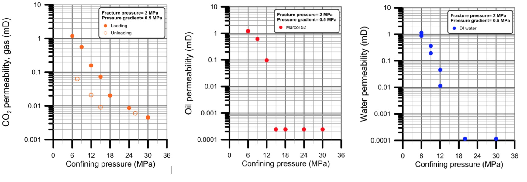
Fig. 2. Fracture permeability (mD) of a fractured Draupne shale sample as a function of confining pressure for different fluids, CO2 gas (left), oil (middle), and water (right).
1.4 Characterization of shale exposure to scCO2 (IFE) During CO2-storage, the shale caprock mainly comes into contact with the supercritical CO2 bubble, rather than with CO2 dissolved in water. Investigations of the resulting physical and chemical interactions between dry or wet supercritical CO2 and clay minerals, plus any organic matter present in the caprock, have been performed to determine if these interactions may affect caprock integrity.
As described in Effect of CO2 on shale caprock integrity (99 downloads ) , shale rock samples were exposed to dry and hydrous supercritical CO2 at typical reservoir temperature and pressure. No significant changes in shale composition were observed when exposed to scCO2 under these conditions. Some shale samples (unconfined) exhibited swelling behavior and microcracking during the dehydration experiments. These structural observations (seen in Fig. 3) are the subject of future investigations.
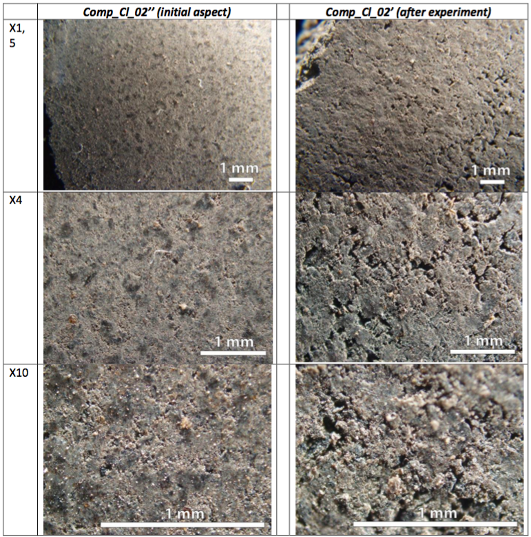
Fig 3. Images of the shale tablet surface before and after exposure to CO2.
1.5 Core-flooding fracture mineralization (UiO):
A series of microfluidic experiments have been performed to investigate how salt crystals, precipitated in the fractures, can affect the flow inside the fractures (Nooraiepour, H. et al., Effect of CO2 Phase States and Flow Rate on Salt Precipitation in Shale Caprocks—A Microfluidic Study. ES&T 2018). During these experiments laser-scribed samples of organic-rich Draupne shale samples are used as the substrate to represent the real fractured rock. CO2 in three phases (gas, supercritical and liquid) is injected into the sample at different field-relevant injection rates so that the dynamics of salt precipitation is visually observed. The development of micrometer-sized salt crystals toward the inlet of the fracture (Fig. 4), the affinity of salt bodies to become connected, and extent of accumulations suggest that the salt precipitation during injection of CO2 into the geological formations can be considered as a fracture healing mechanism.

Fig. 4. Dynamics of salt precipitation for micrometer-sized crystals of halite that form on the interface of rock and CO2 stream. The subfigures are time-lapse images of an experiment at pressure = 1 MPa, temperature = 22 °C, and flow rate = 20 cm3 CO2/min. The white-outlined surfaces describe the fracture walls, and the blue-outlined areas inside the fractures are precipitated salt crystals.
1.6 Joint inversion of geophysical data (NGI/Uni): This task consists of two sub-tasks (1) gravimetric data inversion for leak detection (NGI) and (2) joint inversion of seismic and CSEM data (Uni).
Joint inversion of seismic and CSEM data types (Uni) — 4D seismic data is the gold standard of monitoring large-scale CCS projects. Standard inversion of seismic data has difficulties discriminating between signals from saturation and pressure changes. Joint utilization of PP seismic with PS seismic, electromagnetic (EM) or gravimetric signals has the potential to differentiate saturation from pressure, and thus may greatly improve the value of PP seismic surveys ( Discriminating time-lapse saturation and pressure changes in CO2 monitoring from seismic waveform and CSEM data using ensemble-based Bayesian inversion (116 downloads ) ). A methodology where results from EM or gravimetric inversion are utilized in the prior model for seismic inversion has been developed (Fig. 5) and tested on the Skade formation synthetic data study (Fig. 6) with advantageous results ([1] Tveit S, Mannseth T, Park J, Sauvin G, Agersborg R. Combining CSEM or gravity inversion with seismic AVO inversion, with application to monoitoring of large-scale CO2 injection. Geophysical Journal International 2018, submitted).
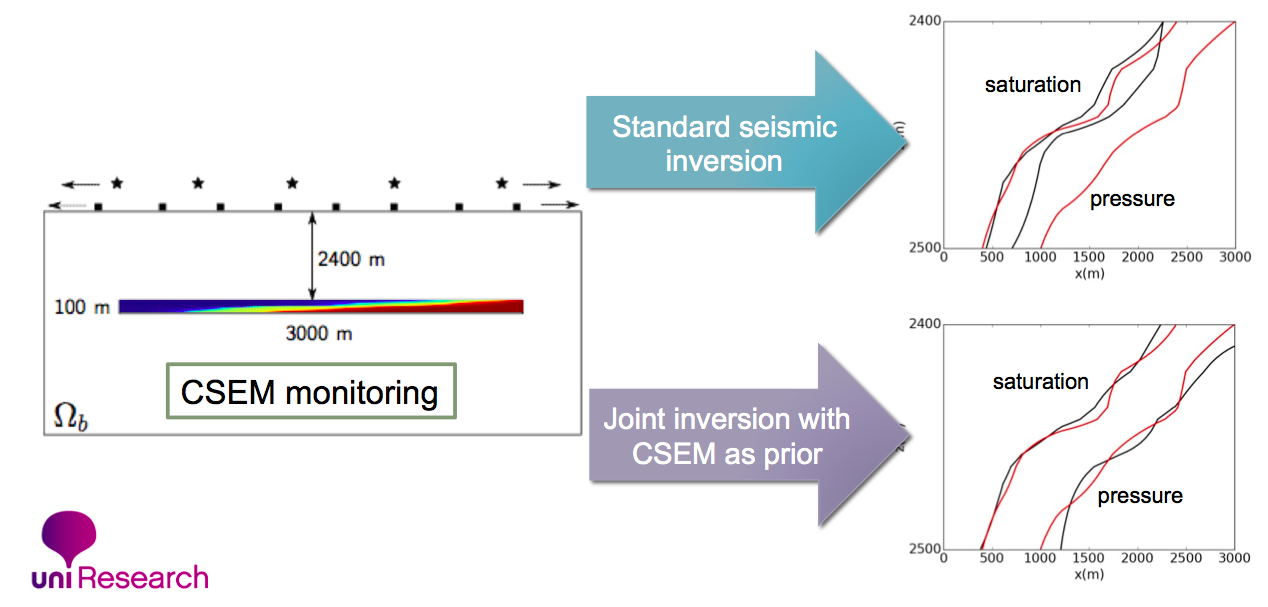
Fig 5. Improved seismic data interpretation through joint inversion with CSEM.

Fig. 6. Vertically exaggerated cross section of seismic inversion of synthetic data from the Skade formation [12]. Panels show seismic P-velocity. Left: true Vp. Middle: mean estimate using seismic data only. Right: mean estimate using novel methodology with seismic and gravimetric data.
Gravimetric data may be used alone or in combination with seismic and/or electromagnetic (EM) to detect CO2 leaked from an injection plume. Investigations using data from the Utsira Sleipner CO2 injection site were used to determine the effectiveness of gravity data for leak detection. Results show that gravity data alone is insufficient for leak detection. Densely sampled (<<1km) gravity data (with noise of ca 3 mGal) can be used to measure density of leaked plumes only if plume position is given by seismic data (Viken I, et al. Feasibility study of gravity data for monitoring CO2 leakage in overburden (52 downloads ) NGI Report 20130614-01-R, 26 November 2014).